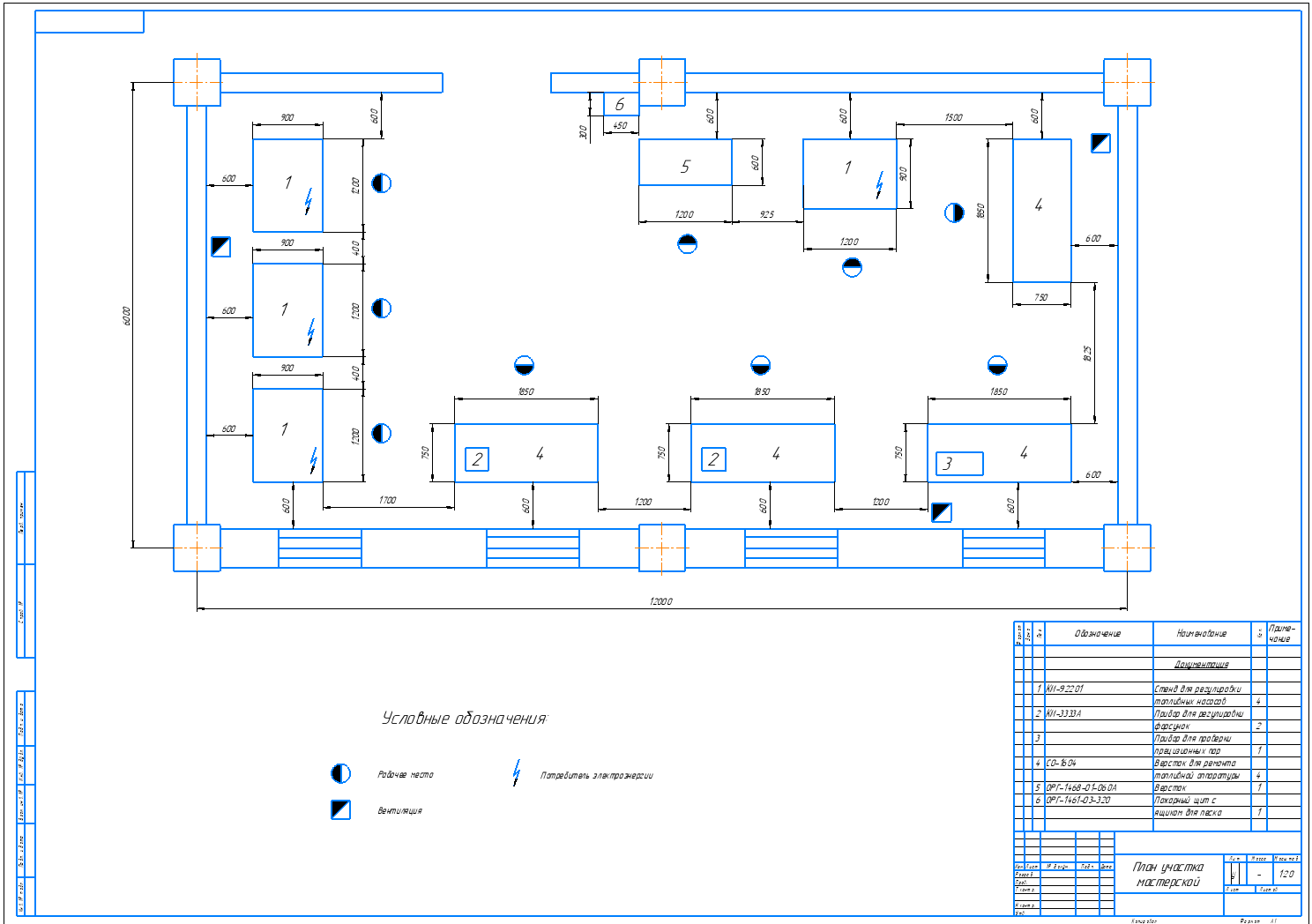
Organization of maintenance and repair of the tractor fleet with the development of the section of maintenance and repair of fuel equipment of diesel engines with the technology of repair of the plunger pair

- Added: 23.05.2021
- Size: 1 MB
- Downloads: 12
Description
6.1 Description of Structural Design
The structural design presents a stand for checking and repairing plunger pairs.
Figure 11 - Devices for pressure testing of plunger pairs: 1 - base; 2 - pallet; 3 - screw wrench; 4 - screw; 5 - bearing 6 - housing; 7 - plunger bushing; 8 - screw-retainer of plunger bushing; 9 - installation head; 10 - lever; 11 - roller; 12 - nut; 13 - fuel tank; 14 - rack; 15 - bushing.
This device allows you to check the condition of precision plunger pairs of TNVD. To this end, the device adapter is connected to the high-pressure fuel line of the tested section, the full fuel supply is switched on, the engine crankshaft is rotated with a starter, and the pressure generated by the plunger pair of the tested section is determined using the pressure gauge of the device.
The obtained data are compared with the standard. Then, without disconnecting the device from the HPLC section, it is possible to check the condition (tightness) of the pressure valve of the section when the engine is not operating, but the fuel supply is turned on. Using lever-handle of the device create pressure of 0.15-0.20 MPa (150-200 kgf/cm2) - the valve must not pass fuel for 30 seconds (pressure must not drop).
Project's Content
|
|
|
|
|
|
|
|
|
|
- Kompas or KOMPAS-3D Viewer
- Microsoft Word
Additional information
![]() 3.cdw
3.cdw

![]() Диплом Усков.docx
Диплом Усков.docx
![]() 4.cdw
4.cdw

![]() 1.cdw
1.cdw

![]() 2.cdw
2.cdw

Similar materials
- 02.05.2021
- 24.01.2023
- 28.03.2021
- 29.04.2021
- 01.06.2019
- 25.10.2022
- 24.01.2023


