Design of a mechanical assembly shop for the production of KAMAZ transfer cases


- Added: 29.01.2022
- Size: 11 MB
- Downloads: 0
Description
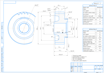
The project includes an explanatory note for 52 pages, 16 illustrations, 12 tables, 6 sheets of A1 drawings.
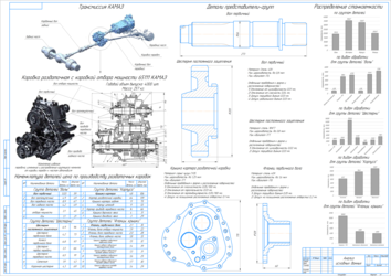
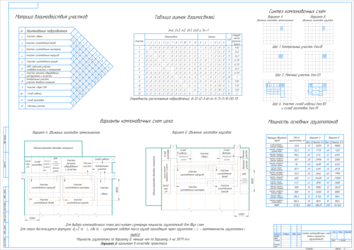
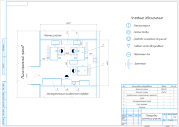
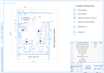
During the design process, a project of a mechanical assembly shop for the production of transfer cases of KAMAZ trucks for medium-scale production conditions was developed. The initial data were the program for the production of shop parts, the assembly drawing of the transfer case and its components, as well as drawings of the primary shaft and the gear of the intermediate shaft. When analyzing the initial data, the parts of the transfer case are divided into groups with similar design features, the machine consumption is determined by types of equipment for each group. In the technological part, the layout plan of the workshop, the gear manufacturing site, the equipment repair site, and the sharpening section have been developed.
The project presents power calculations and constructive study of the machine tool for gear grinding, which provides mechanized fixation of the workpiece and a reduction in auxiliary time.
Project's Content
|
|
|
|
|
|
|
|
|
|
|
|
|
|
|
|
|
|
|
|
|
|
|
|
|
|
|
|
|
|
|
|
|
|
|
|
|
|
|
|
|
|
|
|
|
|
|
|
|
|
- Kompas or KOMPAS-3D Viewer
- Adobe Acrobat Reader
- Microsoft Word
- Program for viewing images
Additional information
Contents
SUMMARY
1. PROCESS PART
1.1. Description of the object of production
1.2. Development of a technological complex for the production of transfer boxes
1.2.1. Analysis of labour intensity and machine-tool capacity of shop parts manufacturing. Calculation of the total quantity of workshop process equipment
1.2.2. Select Site Specialization
1.2.3. Calculation of number of machines, workplaces, area and number of working production areas of the workshop
1.2.4. Calculations of support offices and development of options for their placement
1.2.5. Defining the Concept of Building Layout Variants
1.2.6. Development of the unit interaction matrix
1.2.7. Selection and justification of the type and main construction parameters of the production building
1.2.8. Development of the layout plan of the workshop
1.2.9. Shop Cargo Flow Analysis
1.2.10. Calculation of the number of machines, the number of workers, the production area of the shaft section
1.2.11. Development of equipment repair area layout
2. DESIGN PART
2.1. Design of dental appliance
2.1.1. Refine the workpiece installation scheme. Development of fixture diagram
2.1.2. Drawing up a diagram of the forces acting on the workpiece. Calculation of fixing forces
2.1.3. Selection of clamping devices
2.1.4. Purpose of technical requirements for the accessory ensuring their accuracy
2.1.5. Description of the structure and operation of the accessory
LIST OF SOURCES USED
Summary
The project includes an explanatory note on p., 16 illustrations, 12 tables, 6 sheets of drawings in the format A1.
During the design process, the design of the mechanical assembly workshop for the production of transfer boxes of the KAMAZ truck for medium-sized production conditions was developed. The initial data were the production program of the workshop parts, the assembly drawing of the transfer box and its components, as well as the drawings of the primary shaft and the gear of the intermediate shaft. When analyzing the initial data, the parts of the dispenser box are divided into groups with similar structural features, the machine capacity for the types of equipment for each group is determined. In the process part, the layout plan of the workshop and the gear manufacturing area were developed .
The design presents power calculations and structural development of the machine tool for gear tooth processing, which provides mechanized fastening of the workpiece and reduction of auxiliary time.
Process Part
Select Site Specialization
When you select an organization form, consider the following: According to the technological principle, workshops are mainly formed at enterprises of single and small-scale production, producing a diverse and unstable range of products. As the specialization of production develops, as well as the standardization and unification of products and their parts, the technological principle of the formation of workshops is usually supplemented by an object one, in which the main workshops are created on the basis of the manufacture of each of them of a certain product or its part.
The subject form of the organization of workshops is characteristic of plants with subject specialization. Parts or products attached to them are fully manufactured in the workshops. Workshops with an object form of organization are characterized by a variety of equipment and accessories, but a small range of parts or products. The equipment is selected according to the process and is located depending on the sequence of operations, that is, the principle of straightforwardness is used. This formation of workshops is most characteristic of mass production and mass production enterprises.
The advantages of the object form of the organization include the simple coordination of the work of the workshops, since all the operations for the manufacture of a specific product (part) are concentrated in one workshop. All this leads to a stable repeatability of the production process, to an increase in the responsibility of the shop manager for the production of products within the established time frame, the required quantity and quality, to simplify operational and production planning, to reduce the production cycle, to reduce the number and variety of routes of labor objects, to reduce the loss of time for re-installation of equipment, reduction of interoperative time and elimination of inter-household lying, creation of conditions, favorable for the introduction of in-line production methods, integrated mechanization and automation of production processes. The experience of enterprises shows that in the subject form of the organization of workshops, the above advantages lead to an increase in the productivity of workers and the rhythm of production, to a decrease in the cost of production. Taking into account the above, the substantive form of the organization has been adopted.
Selection and justification of the type and main construction parameters of the production building
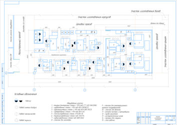
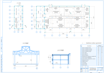
The design area of the designed workshop is 4666 m2. Let's choose a column grid with dimensions of 24x12 m, and the dimensions of the building are 72x72 m. At the specified parameters, the area will be 5184 m2, which is more than enough to accommodate the designed workshop .
Bridge crane is used for internal movement of housings, covers and assembly units. The height of the span of the crane building can be 10.8 m, 12.6 m depending on the dimensions of the manufactured products. The value of 10.8 m is determined. A roof with light-aeration lights will increase the amount of transmitted light inside the building, as well as improve ventilation, which in total will have a favorable effect on the working conditions of workers .
The area of office and household premises is 1565 m2. For their placement, unified typical sections with a grid of columns of 6x6 m are used. The width of the extension is 12 m, the length is 36, 48 and 60 m. The area of the three-story extension with dimensions of 12x48 m will be 1728 m2, which is enough to accommodate service and household units.
Design Part
Purpose of technical requirements for the accessory ensuring their accuracy
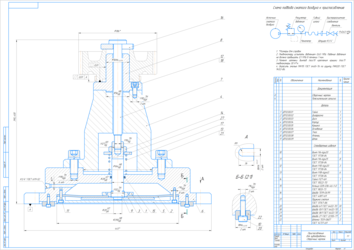
The following technical requirements are assigned to the accessory:
Deviation from parallel of flange mounting plane (pos.8) relative to surface A is not more than 0.01 mm.
Deviation from perpendicular of flange surface Ø56h6 (pos.8) relative to flange mounting plane is not more than 0.01 mm.
Test the pneumatic drive with pressure of 0.63 MPa. Pressure drop shall not exceed 0.1 MPa during 1 min.
Tightening torque of screws (pos.13) of pneumatic chamber cover attachment (pos.6) is 30 N * m.
Paint with PF115 enamel, GOST 646576, as per PF020 soil, GOST 945286.
Purpose of material and heat treatment for accessory parts.
We will select the material and type of heat treatment of the parts based on their operating conditions when fixing the assembly unit.
Part: base (pos.6), flange (pos.8).
Material: steel 20X GOST 4543-71
Working surfaces shall have increased wear resistance. To do this, they undergo cementation with subsequent hardening.
Heat treatment: cementation, hardening (contacting places 51.560 HRC, the remaining 36.541.5 HRC).
Description of the structure and operation of the accessory
Device has vertical arrangement and consists of three parts. The first part is a pneumatic chamber formed by the base (pos.6), cover (pos.5), diaphragm (pos.2), rod (pos.9), disk (pos.3), washer (pos.1). The base is the base part of the fixture and has a reference plane A on which the fixture is based on the machine table. Also, two slots are provided on this plane, in which keys with width of 18h6 are based and attached by screws M6 (pos.10). In addition, two through slots with width 18H14 are provided on said plane for attachment of the device. On the side of this plane there is a cavity that is closed by the cover (pos.6), the cover is attached by eight screws M6 (pos.13) and, thus, pinches the fabric diaphragm (pos.2) between the body and the cover. Rod (12) comes out of pneumatic chamber to its lower end by means of disk (3) and washer (11) the center of diaphragm (2) is attached. Thus, the diaphragm divides the chamber into two upper and lower parts. Air is supplied to the upper cavity through the hole K1/4, "the diaphragm is deformed and pulls the rod (pos.9) down. The rod passes through the second part of the accessory formed by the housing (pos.4), which is attached to the base (pos.6) by six bolts M18 (pos.13) and is based on the fit of the ∅164H8/h8. In the housing there is a through stepped hole through which the rod passes (pos.9). Nut (pos.27) is screwed onto the rod, against the end face of which the spring rests, with the second end the spring rests against the base (pos.6). Spring is used for return of rod (pos.9) and diaphragm (pos.2) to initial position after pressure relief in pneumatic chamber. Rod (pos.7) is screwed into rod (pos.9), which passes through hole in flange (pos.8). Flange (item 8) form the third part of the accessory intended for the workpiece basing. The flange (poses.8) is installed in the case (poses.4) on landing of Ø56H8/h8 and fastens by means of M10 screws (poses.12). A quick-release washer (pos.16) is installed on the end of the blank, which presses the blank to the flange (pos.8).
The modular arrangement of the device ensures its quick and simple assembly, as well as disassembly for the purpose of repair or replacement of component parts. In addition, by replacing the flange (item 8), it is possible to re-install the device for manufacturing another gear wheel, which is very important in the conditions of mass production. The removable housing (pos.4) provides a potential opportunity to change over the accessory, in principle, for the manufacture of another type of parts. The main task in remapping is to ensure the mutual position of the base surfaces with a given accuracy, which can be achieved by accurately manufacturing these parts or processing the base surfaces assembled .
Before installation/removal of the workpiece the washer is removed (pos.16). After that, the operator sets the workpiece along the surface Ø56 and the end of the sleeve (pos.8). After that, washer (pos.16) is placed on billet end face and air is supplied to pneumatic chamber. Push-pull rod (pos.7) together with rod (pos.9) moves downwards, securing the workpiece. After processing it is necessary to turn off the air supply, and the rod (pos.9) under the action of the spring rises upwards, detaching the workpiece. After that remove washer (pos.16) and blank.
![]() КП ТМ 11 сем РК Лист 5 Участок шестерней.cdw
КП ТМ 11 сем РК Лист 5 Участок шестерней.cdw
![]() КП ТМ 11 сем РК Лист 6 Приспособление.cdw
КП ТМ 11 сем РК Лист 6 Приспособление.cdw
![]() КП ТМ 11 сем РК Лист 1 Анализ исходных данных.cdw
КП ТМ 11 сем РК Лист 1 Анализ исходных данных.cdw
![]() КП ТМ 11 сем РК Лист 2 Синтез компоновок.cdw
КП ТМ 11 сем РК Лист 2 Синтез компоновок.cdw
![]() КП ТМ 11 сем РК Лист 3 Компоновка цеха.cdw
КП ТМ 11 сем РК Лист 3 Компоновка цеха.cdw
![]() КП ТМ 11 сем РК Лист 4 Заточной участок А2.cdw
КП ТМ 11 сем РК Лист 4 Заточной участок А2.cdw
![]() КП ТМ 11 сем РК Лист 4 Участок ремонта оборудования А2.cdw
КП ТМ 11 сем РК Лист 4 Участок ремонта оборудования А2.cdw
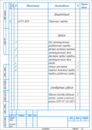
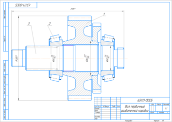
![]() Вал первичный раздаточной коробки.spw
Вал первичный раздаточной коробки.spw
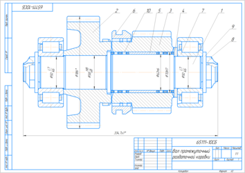
![]() Вал промежуточный раздаточной коробки.spw
Вал промежуточный раздаточной коробки.spw
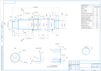
![]() Вал.cdw
Вал.cdw
![]() Вал_первичный_СБ1.cdw
Вал_первичный_СБ1.cdw
![]() Вал_промежуточный_СБ.cdw
Вал_промежуточный_СБ.cdw
![]() Шестерня.cdw
Шестерня.cdw
Similar materials
- 24.04.2014
- 24.04.2014
- 24.04.2014


